Zega Mame Boy Advance Solder Guide
Top Side
PWR: LED (RED)
ACT: LED (GREEN)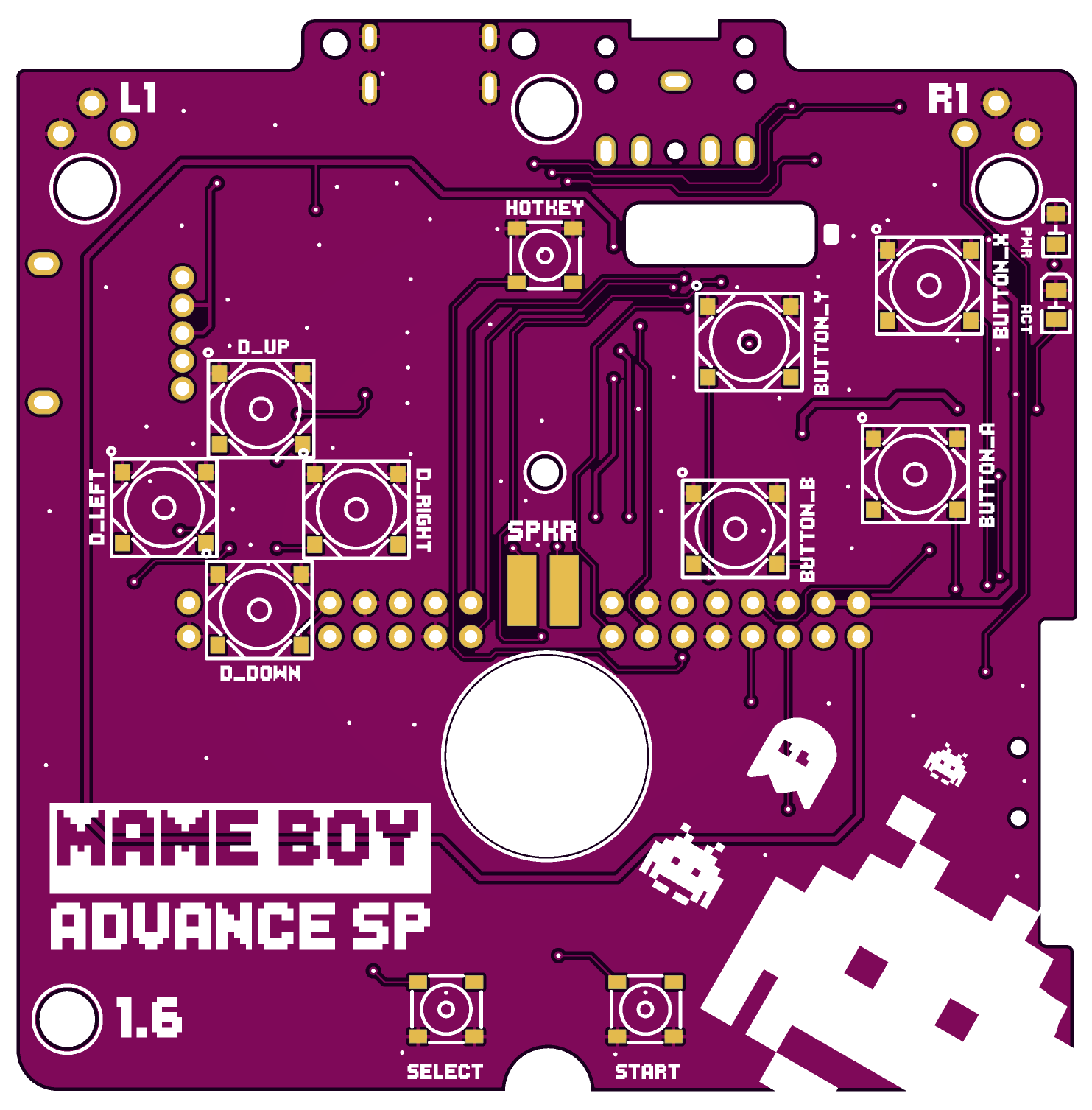
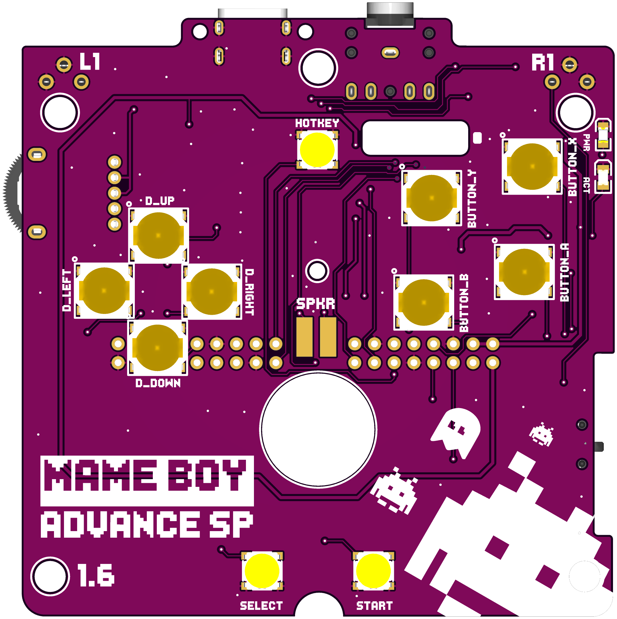
ACT: LED (GREEN)
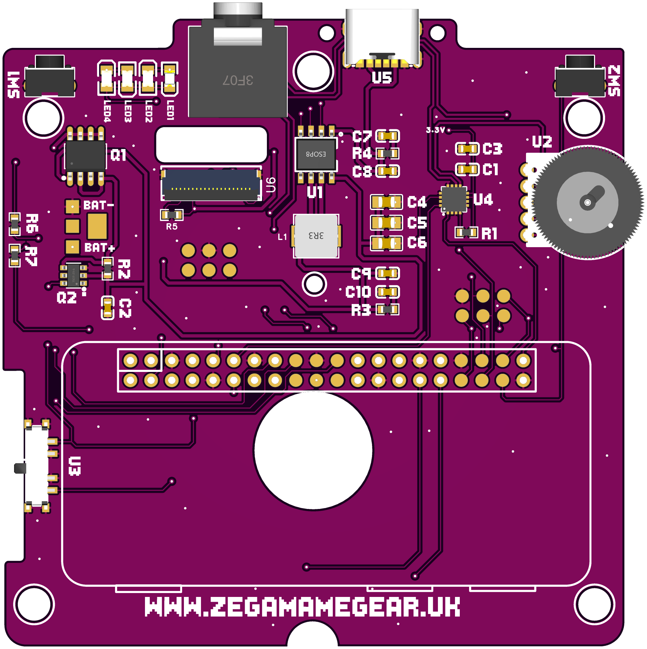
Bottom Side
LED1 - LED (RED)
LED2, LED3, LED4: LED (GREEN)
LED2, LED3, LED4: LED (GREEN)
SW1, SW2: Trigger
R1: 1MΩ
R2, R6, R7: 2KΩ
R3, R4: 2Ω
R5: 10Ω
C1, C2, C7, C8, C9, C10: 10uF
C3: 100nF
C4, C5, C6: 22uF
Q1: SS (Safe Shutdown) IC
Q2: YN810
U1: BATTERY IC (Visible Ground layer on bottom of IC)U6: 20 Pin FPC Connector
U2: Volume Wheel
R1: 1MΩ
R2, R6, R7: 2KΩ
R3, R4: 2Ω
R5: 10Ω
C1, C2, C7, C8, C9, C10: 10uF
C3: 100nF
C4, C5, C6: 22uF
Q1: SS (Safe Shutdown) IC
Q2: YN810
U1: BATTERY IC (Visible Ground layer on bottom of IC)U6: 20 Pin FPC Connector
U2: Volume Wheel
U3: ON-OFF SWITCH
U5: USB-C Connector
U4: AUDIO IC
L1: 1uH Inductor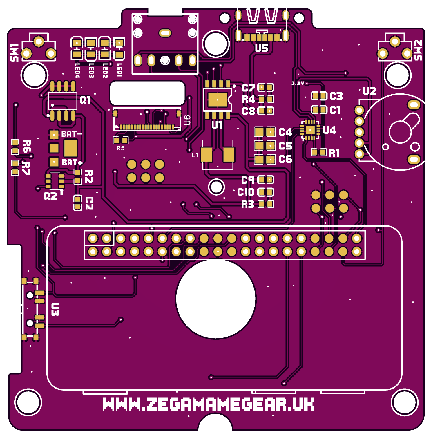
U5: USB-C Connector
U4: AUDIO IC
L1: 1uH Inductor
Related Articles
Zega Mame Boy Pre-install Checks
Installation of the Zega Mame Boy+ requires soldering to complete the setup. Only attempt if you are confident in your soldering ability. By attempting to complete the setup of the Zega Mame Boy+ you are confirming that you accept responsibility for ...Zega Mame Gear Pre-install Checks
Power Board Connect the power board to a USB-C power source Ensure the battery level LEDs illuminate Mainboard Disconnect the USB-C power supply Connect the Power Board to the Mainboard using the supplied 4 pin connector Toggle the power switch ...Preparing your SD Card
How to download and flash an SD card for your device To prepare an SD card to use in your device you will need An SD Card (Minimum 8GB) A copy of either Balena Etcher, Win32DiskImager or Raspberry Pi Imager Download the required image from the Zega ...ILI9341 Serial LCD Manual Driver Installation
All pre-made images available to download are already configured with this driver You will require: SSH Access to your Raspberry Pi (Putty is recommended) FTP access to your Raspberry Pi (WinSCP is recommended) 1. Connect to your Raspberry Pi using ...